Overview
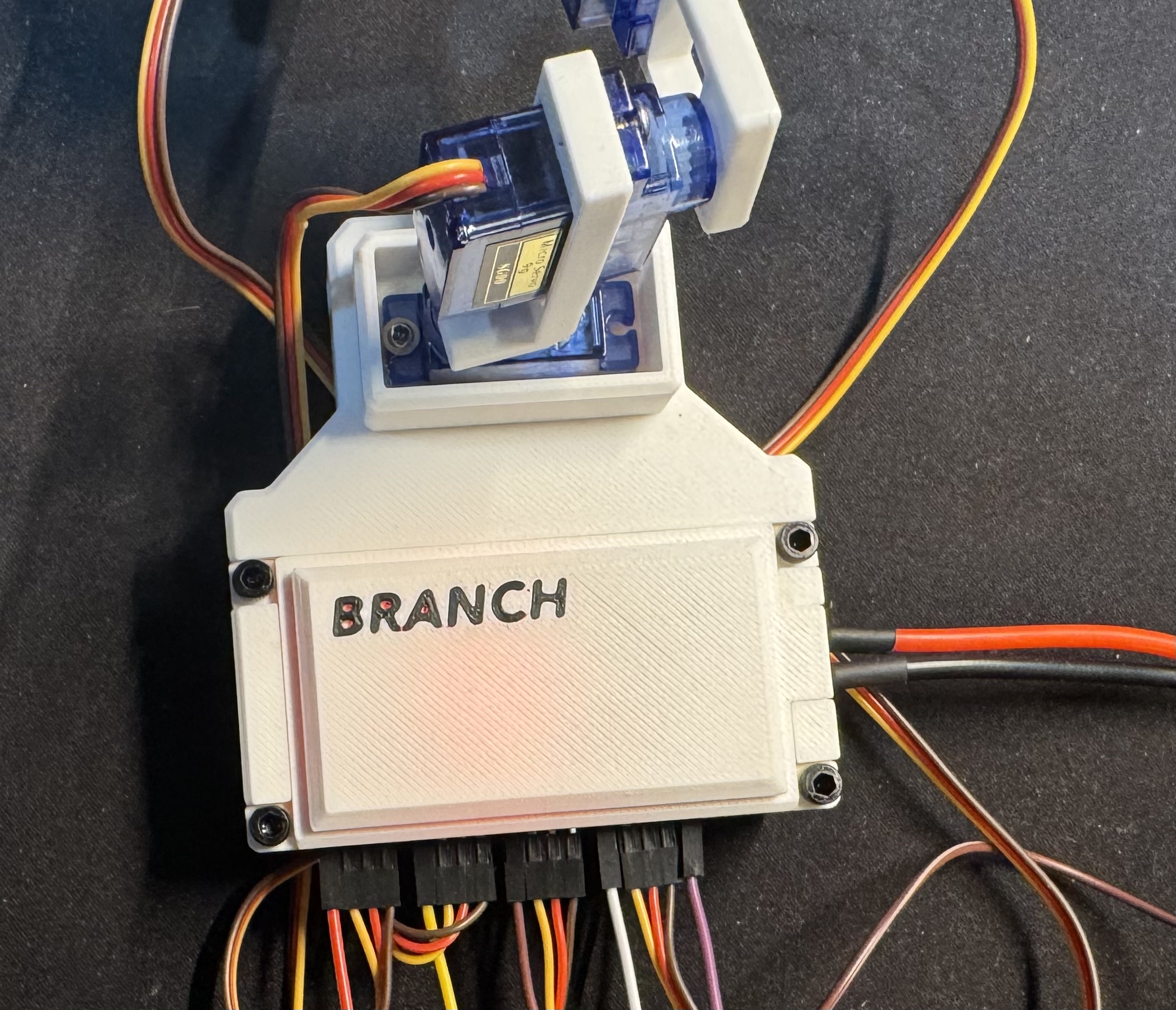
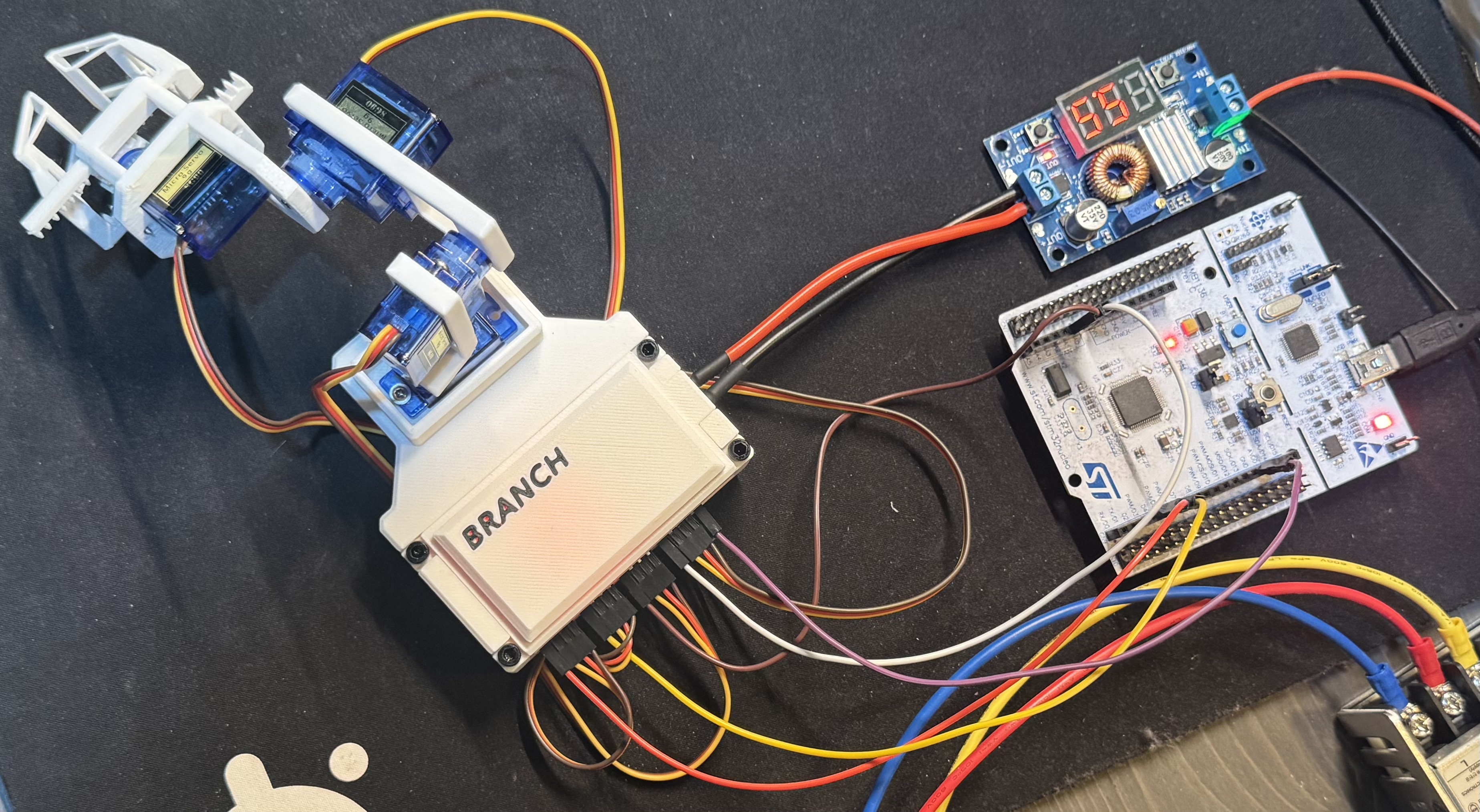
I designed and built a physical 4-DOF robotic arm from scratch, combining embedded software, PCB design, CAD, and 3D printing into a single project. The system uses an STM32 microcontroller to control four servos and a gripper, while a Python host application communicates with the arm over UART.
This project was my first serious attempt at building a robotic system that could physically interact with the world. It was also my first custom PCB and one of my largest CAD projects to date.
Demo
Motivation
After completing several embedded projects, I wanted to build something that could actually move. Reading sensors and collecting data is interesting, but there is something different about watching code turn into physical movement.
Around the same time, I bought a 3D printer. Suddenly robotics projects felt much more accessible because I could design and manufacture my own parts instead of trying to work entirely with off-the-shelf hardware.
Since I already had experience with embedded development, a robotic arm felt like a natural next step. It would let me combine software, electronics, CAD, and manufacturing into a single project while learning more about robotics and actuator control.
Technical Highlights
- STM32 Firmware – Real-time PWM servo control with velocity limiting for smoother motion.
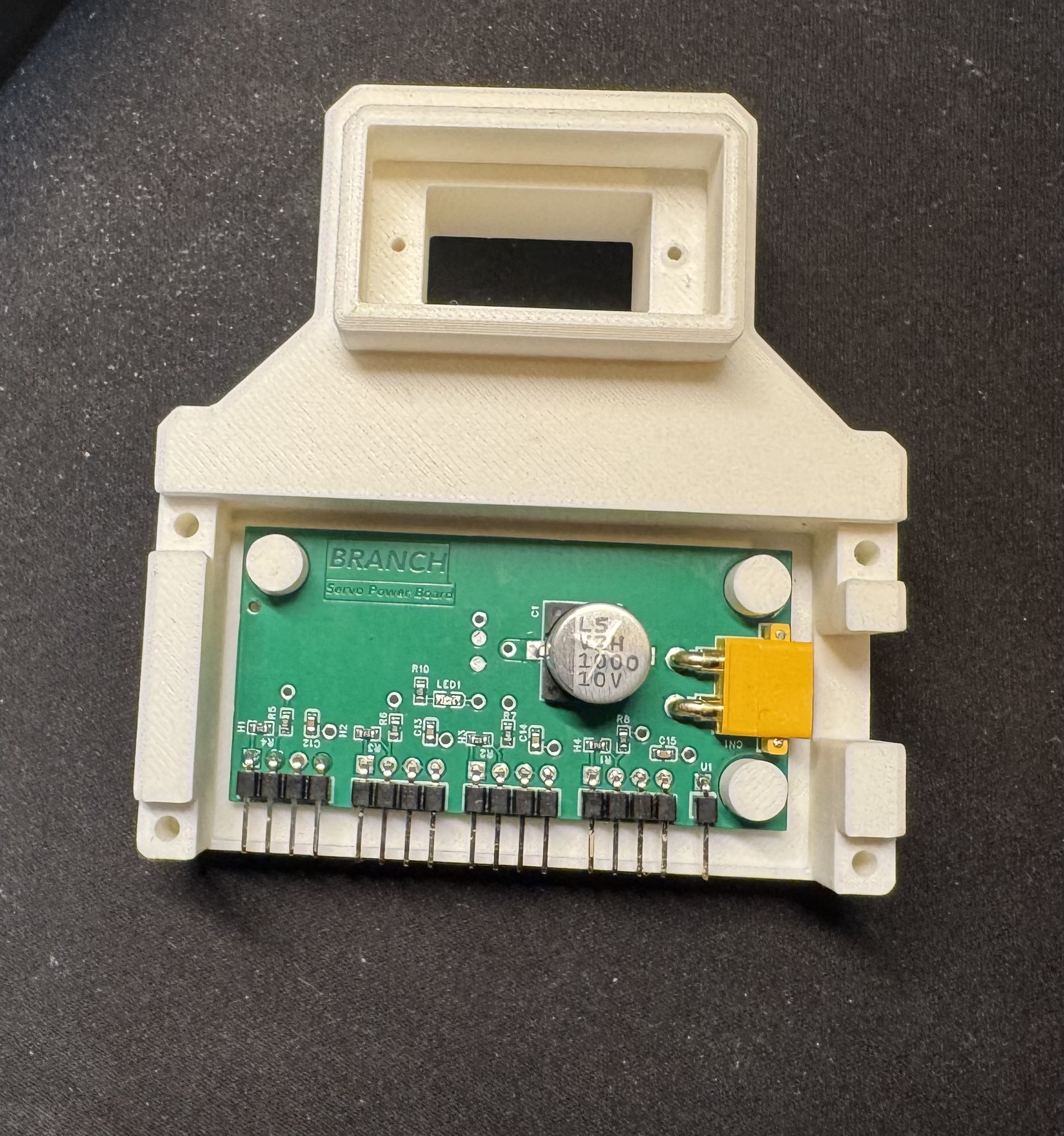
- Custom PCB – Designed a dedicated servo power distribution board to reduce wiring complexity and save space.
- Python Host Interface – UART communication for commanding arm poses and gripper actions.
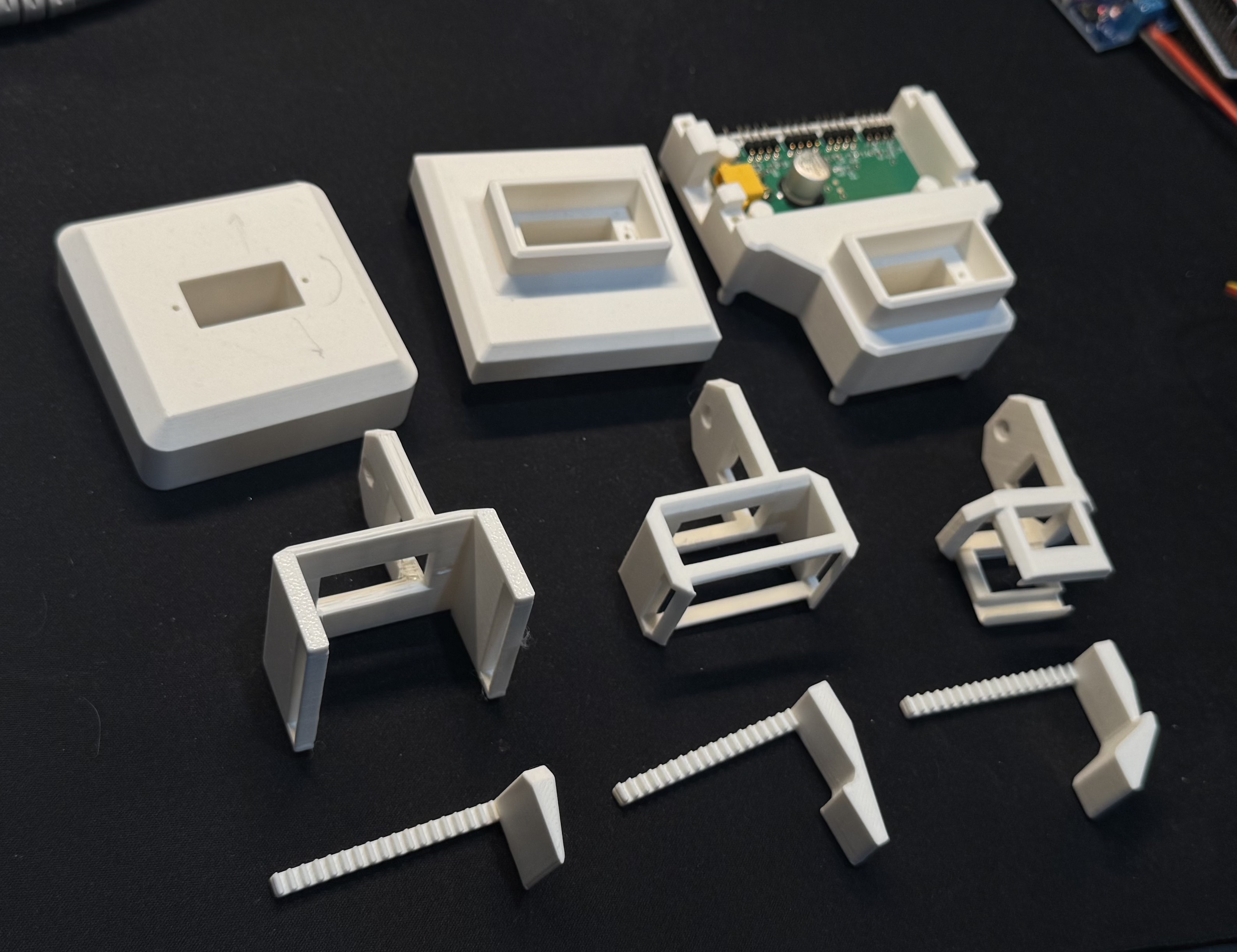
- CAD & Fabrication – Designed all structural components in Fusion 360 and manufactured them with a 3D printer.
- Mechanical Design – Developed a rack-and-pinion gripper and custom servo mounting system.
Mechanical Design & 3D Printing
One of the main design constraints was using a collection of inexpensive 9g servos that I had purchased years ago when I first started learning embedded programming.
While they significantly limited the payload capacity of the arm, they also helped keep the project focused. Instead of immediately jumping to larger motors and more complicated control systems, I could focus on learning the fundamentals of mechanical design and robotics. Looking back, that was probably a good thing because it prevented the project from growing far beyond its original scope.
Before this project, my CAD experience was fairly limited. I had designed a monitor stand for my desk and printed plenty of decorative models, but this was my first time creating a mechanical system where dimensions and tolerances actually mattered.
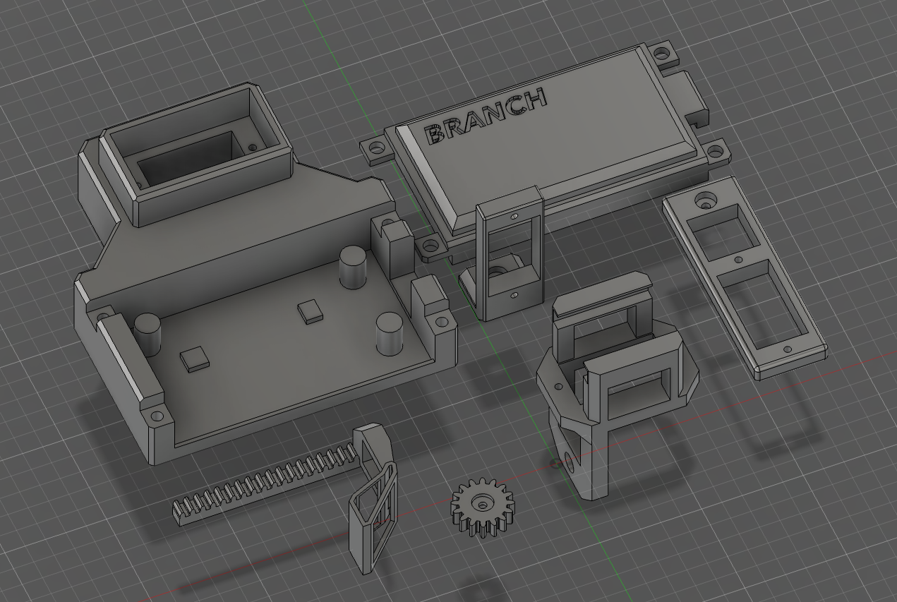
The arm brackets themselves were relatively straightforward. Most of the work involved figuring out the correct dimensions for the servo mounts. Like many engineering problems, this turned into a cycle of printing, testing, adjusting dimensions, and printing again until everything fit properly.
The base went through several revisions throughout development. Initially it was much smaller, but after adding the custom PCB I had to increase its size. In hindsight, that ended up helping because the arm occasionally showed signs of tipping over even after I added speed limits to the motion.
One thing I am still not completely happy with is the accessibility of some of the screws inside the base. It works, but assembly and maintenance are more annoying than they should be.
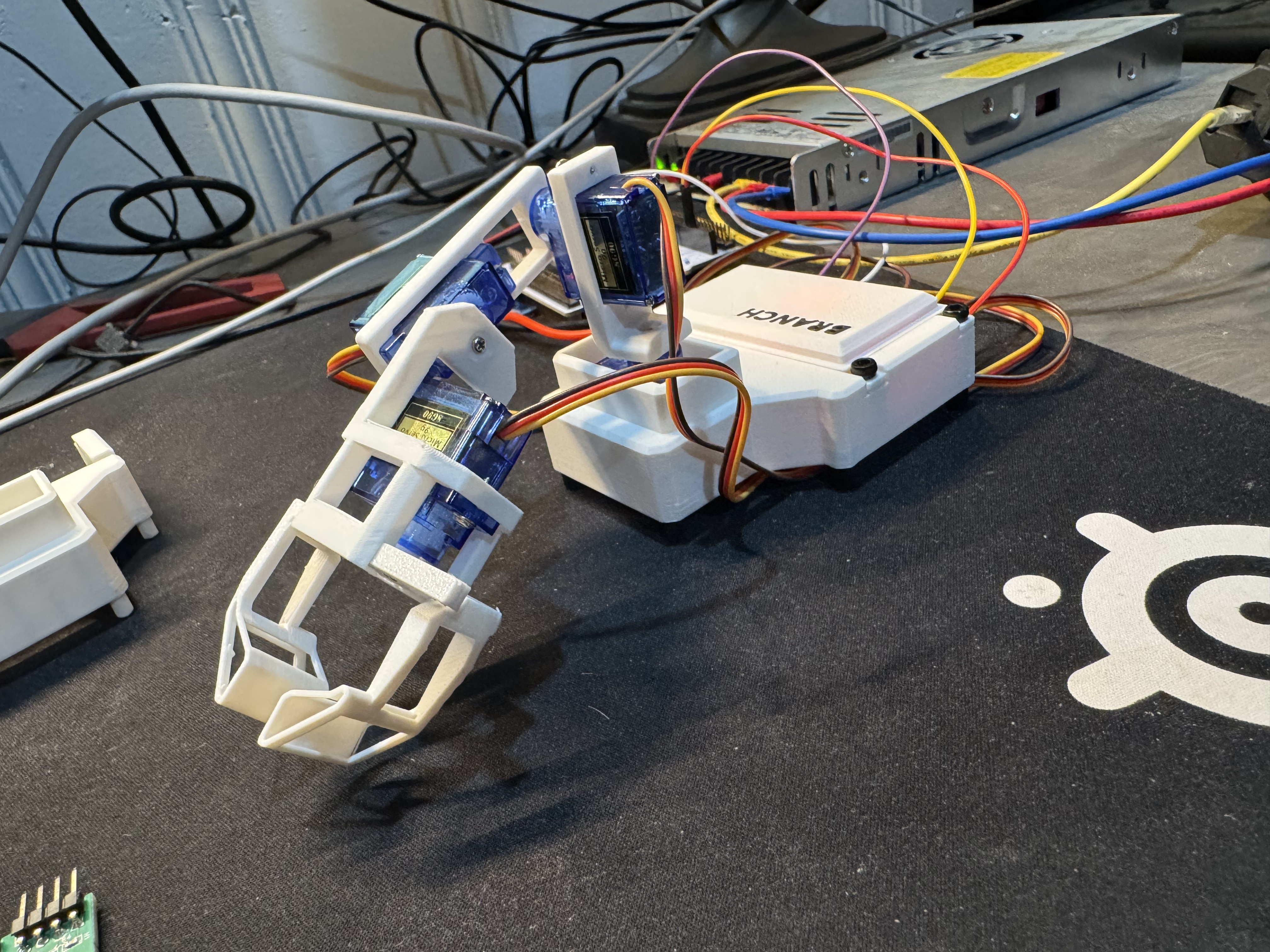
The gripper was by far the most difficult component to design.
The rack-and-pinion mechanism looked simple enough on paper, but getting the racks, gears, and servo aligned correctly required several redesigns. Looking back, many of these issues could have been caught much earlier if I had made better use of CAD assemblies.
One memorable issue involved the racks being roughly 1 mm too short, preventing them from properly meshing with the gears. After adjusting the design and printing new parts, there was still a small amount of play in the system. The final solution was admittedly not very elegant: a tiny folded piece of a gum wrapper used as a shim.
Despite the challenges, I am very happy with how the final gripper and overall arm turned out.
PCB Design
The custom PCB was not part of the original plan.
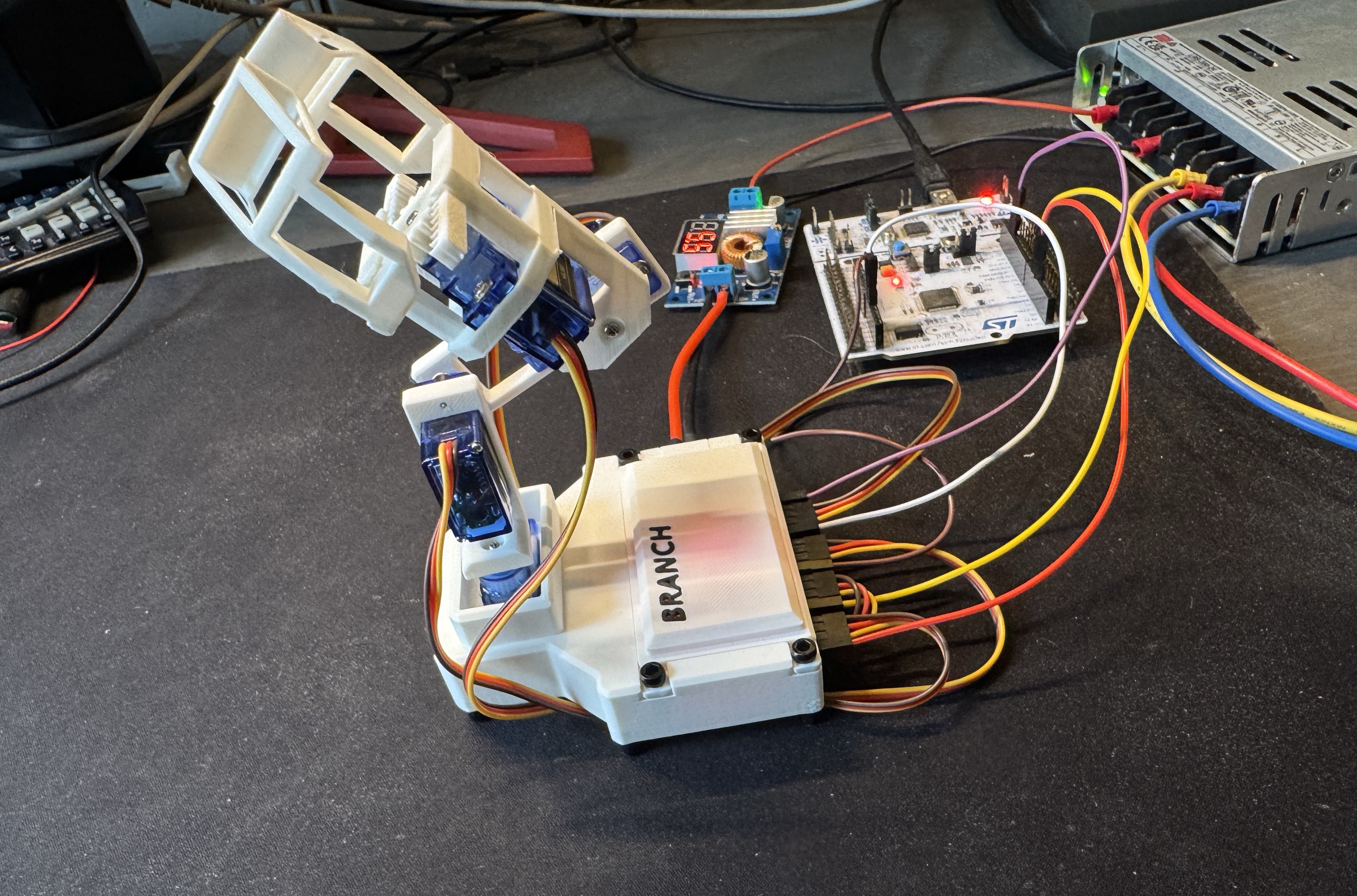
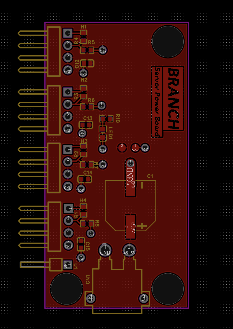
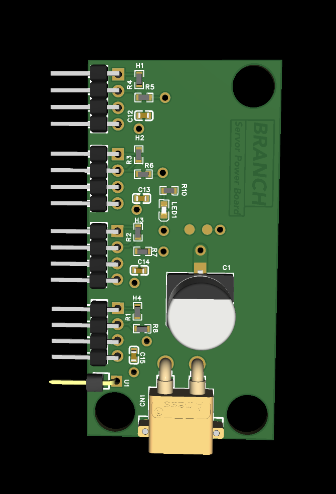
Early prototypes used a buck converter module and terminal blocks mounted inside the base. The setup worked, but it occupied a surprising amount of space and created a mess of wiring. About halfway through the project, I decided it was a good opportunity to finally learn PCB design and create a dedicated servo power distribution board.
I intentionally kept the design simple. Rather than integrating voltage regulation and the microcontroller directly onto the PCB, I continued using existing modules and development boards. At this stage I wanted to learn PCB design itself rather than tackle several new challenges at once.
Designing the board was probably one of the most nerve-racking parts of the entire project.
If I make a mistake in software, I can usually fix it immediately. If I make a mistake in CAD, I can redesign a part and print another copy within a few hours. PCBs are different. Once the order is submitted, there is nothing left to do except wait and hope you did not miss something important.
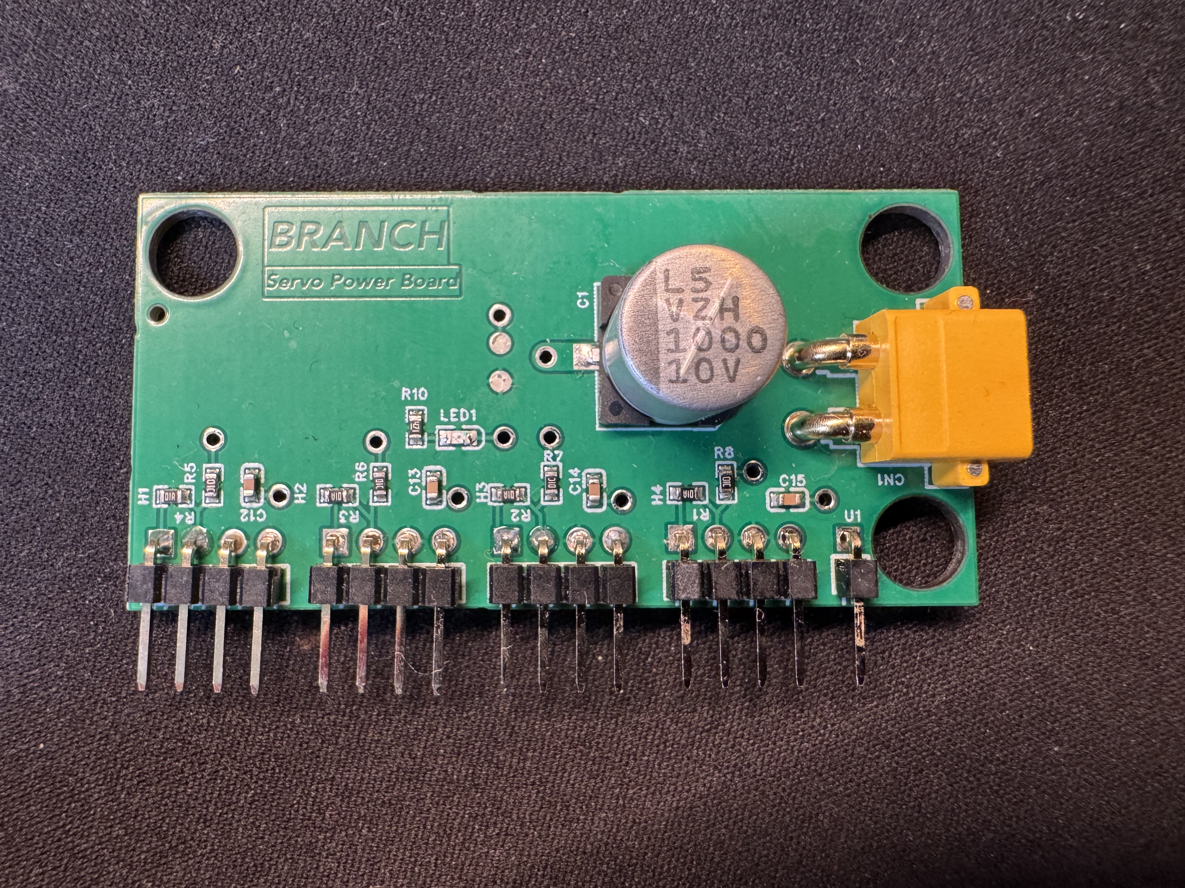
I was impatient enough to pay extra for expedited shipping, which only increased the pressure. After spending several days refreshing the tracking page, the package finally arrived and it was time for the moment every PCB designer knows: plugging it in and hoping nothing catches fire.
Fortunately, the board worked on the first revision.
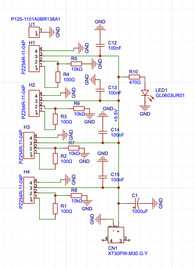
The design also gave me an opportunity to apply concepts I had been learning about electronics design, including decoupling capacitors, power distribution, and copper pours. Prior to this project, I mostly thought of PCBs as collections of traces. Learning about power planes and their role in current distribution and noise reduction was a useful introduction to more advanced PCB design concepts.
Software & Controls
The software side of the project was where I felt the most comfortable.
The STM32 firmware generates the PWM signals used to control each servo and manages communication with the host computer. On the PC side, a Python application sends commands over UART to control arm movement and gripper actions.
Compared to the mechanical and electrical portions of the project, the software architecture was relatively straightforward. Most of the challenges came from integrating everything together and ensuring movement remained smooth and predictable.
Since the servos were relatively weak, adding velocity limits helped reduce sudden movements and made the arm behave much more reliably.
Reflection
Overall, I am extremely happy with how this project turned out.
It was the first project where I truly combined embedded systems, CAD, 3D printing, PCB design, and software into a single working system. Every area presented new challenges, and every area taught me something useful.
If I were starting over today, I would make much heavier use of CAD assemblies and spend more time thinking about maintainability during the mechanical design phase. Several of the fitment issues I encountered could have been identified before printing anything.
Part of me also wishes I had integrated the microcontroller directly onto the PCB. However, that is easy to say now that the project works. For a first PCB design, keeping the electronics modular was probably the right decision.
I occasionally wonder what the arm could have accomplished with larger motors and position feedback sensors. Those additions would have enabled much more advanced control strategies and greater payload capacity, although they also would have increased the complexity and cost of the project significantly.
Regardless of its limitations, seeing the arm successfully pick up and move objects is incredibly satisfying. Watching something move because of hardware and software that I designed myself never really gets old.
What’s Next?
My next major project will be building a custom drone.
The exact scope is still evolving. It may end up being a relatively straightforward manually piloted aircraft, an FPV platform, or something with autonomous capabilities.